Setup
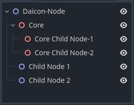
Daicon-Nodes
First of all, let's familiarize ourselves with the new nodes. Each node is a two-dimensional node with a three-dimensional filling. Thus the emphasis between the two spaces falls on the two-dimensionality.
The stuffing is called the core. It is packaged and it is not possible to interact with it directly. To interact with the kernel, the developer is given a panel of parameters containing those that can be changed. There are also the default parameters of the node on which the daikon node is based.
Note
However, if you know what you are doing, you can access the kernel through code. In that case you will have full access to it and all its parameters.
1.First steps
First of all, add a node to your scene that will characterize the scene itself. This is basically a Node, Node2D or Node3D, but the plugin provides a Daicon for this.

Tip
You can continue to use Node, Node2D and Node3D as scene root nodes if you don't need the DaiconNode functionality (more on that on the next page).
Script override
As you may have noticed, there is a script already attached to the node. This is a script file that defines ALL nodes of this type. Thus, it is the same for all of them and can never be edited for local functionality.
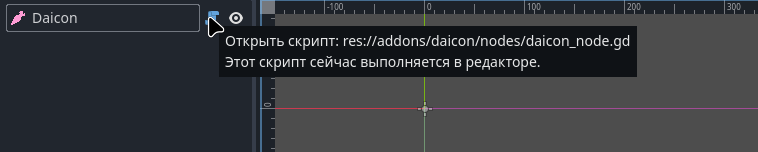
Since all Daicon nodes will be different in your project in the future, you need to extend the script:
- Right click on the node
- In the pop-up menu click on “Extend script” item
- In the script attachment window that opens, check the box next to “Template”.
- Select the template provided by the plugin in advance
- choose a path to save it
- create the script
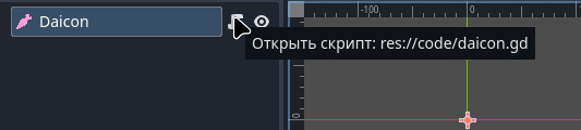
Now your .gd file is overridden and you can rewrite it without affecting the root code of the addon.
Info
When connecting, Daicon creates a templates folder in your project (if it does not exist) or uses an already created one. There it writes templates required for development.
2.Environment
To create an environment, the plugin offers 2 nodes with similar working principle but different purpose:
- DaiconMap (main environment node)
Represents a set of TileMapLayers, which in turn are levels of your environment.
Each such layer contains a unique z-index, which is a measure of the height of this layer in space. In other words, z-sorting places objects along the modulo Z axis based on their index (Y axis in 3D).

- DaiconMapLayer (additional environment node)
Represents a single local independent node TileMapLayer with an embedded core DaiconMap.
So DaiconMapLayer is a support node, or a node representing an individual element of your environment that needs special attention.

Setting up the Environment
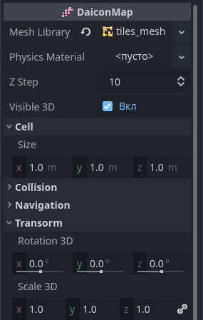
- Mesh Library - a library of meshes from which the 3D world will be constructed
- Physics Material - used to define physical properties, such as friction and elasticity, of individual tiles.
- Z Step - z-index step between height levels
- Visible 3D - visibility of GridMap in 3D
- Cell Size - size in meters for each 3D tile
- Collision Layer and Mask - collision layers for 3D
- Bake Navigation - bake a navigation grid for 3D
- Transform Rotation3D and Scale3D - customize rotation and scale of the core
As you may have noticed, many parameters are missing. This is to ensure the security and correctness of the kernel.
Example
For example, the Transform Position3D section is synchronized with Position2D. When moving a daicon node in its native 2D space, the 3D kernel changes its position accordingly.
Note
Remember, you can always get absolute access to the kernel and all its parameters through code.
Position2D = Vector2D(0, 0); Position3D = Vector3D(0, 0, -0.5)
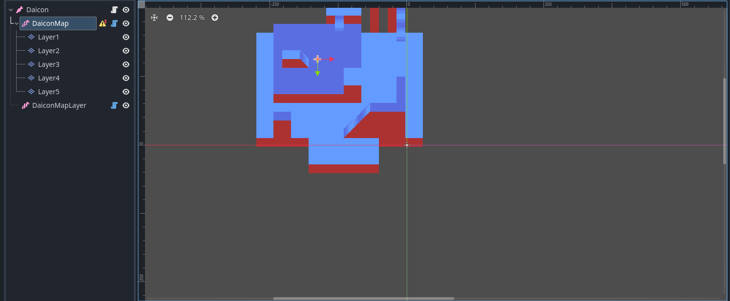
Position2D = Vector2D(-163, -157); Position3D = Vector3D(-10.1875, 0, -10.3125)
The Mesha Library
DaiconMap and DaiconMapLayer necessarily require the mesha library. It is the constructor for the 3D world.
You can use the basic set that comes with it or create your own (see “Manual : Mesh”).
Once the field is filled in, your tiles will have the Item parameter. It binds the corresponding mesh in your mesh library to the tile. Once the tile is placed on the map, the bound mesh will be projected in 3D space.
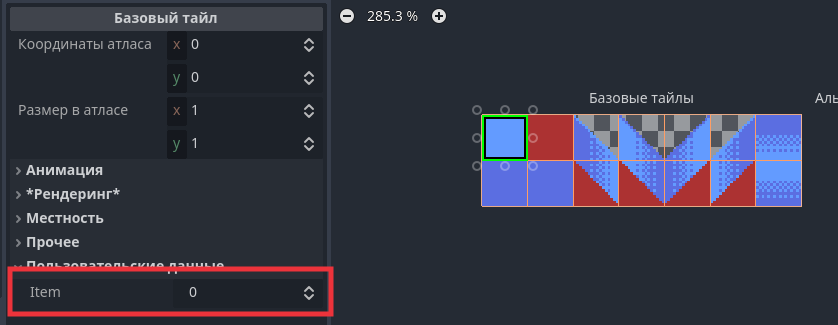
Warning
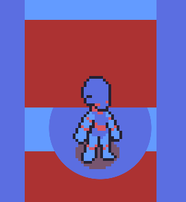
For the side wall tiles (red tiles in the example), set the local z_index = -1. This will eliminate the sorting error when two walls are close to the object.
Creating DaiconMap layers
- Create several layers in the parameter panel for TileMap
- Give them appropriate z-indices
- Go to the TileMap section in the panel at the bottom of the screen
- In the expanded section, click on the tool button in the upper right corner
- Click on “Extract TileMap layers as separate TileMapLayer nodes” option
Now you have environment layers that are full-fledged TileMapLayers nodes.
You can also add new layers as child nodes to DaiconMap. In this case, you will need to carefully monitor the y-sort-enabled = true parameter.
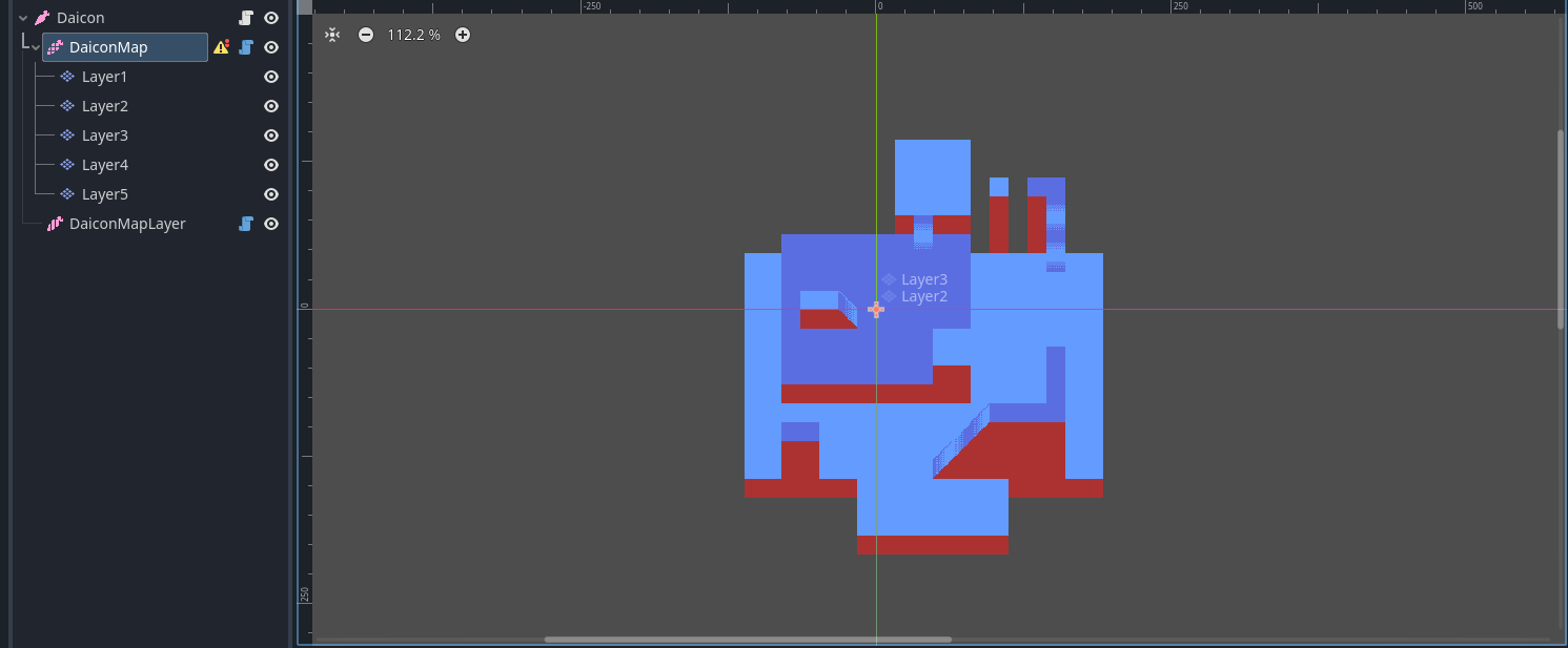
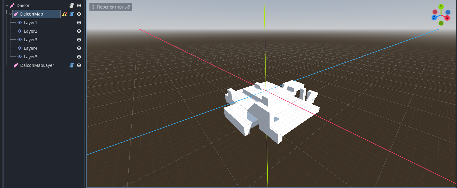
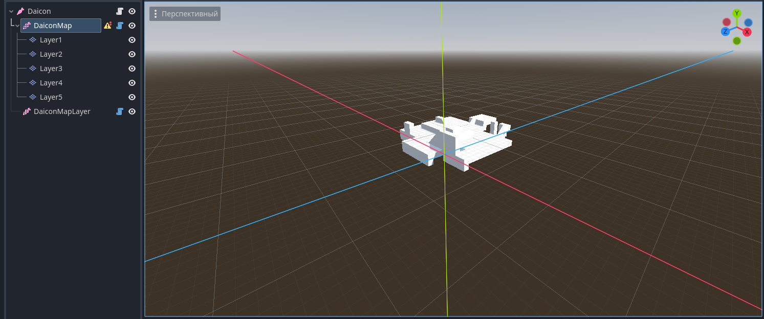
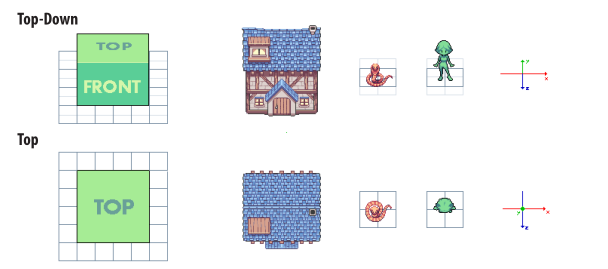
As soon as you draw environments on at least one layer, it will appear in 3D. It is important to realize that, given the projection, each layer above 0 is moved forward by one value, and each layer below it is moved backward by one. This creates a tilted perspective (Top-Down).
If it wasn't, the perspective would be a perfect view from the top (Top)
Warning
This way of working has its own rendering rules. Pay attention to the order of each layer's tiles:
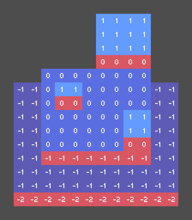
The lower the layer, the darker the color
Red - side of blocks
The number indicates the height level of the layer. To find out the z-index, simply multiply the level by the Z Step.
3.Player
The KinematicDaicon node is used for all kinematic objects. It contains everything necessary to create a moving and interacting object.

Create a player:
- Add a KinematicDaicon to your scene
- Extend the node script:
- Right click on the node
- Select “Extend script”.
- Use the template provided by the plugin for KinematicDaicon
- Select a save path
- Create a new script
Player Setup
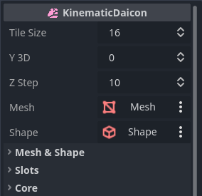
- Tile Size - determines how many pixels equal 1 meter in 3D. (basically it is the tile size per cell size in 3D)
- Y 3D - position of the character on the Z axis (Y axis in 3D)
- Z Step - z-index step between height levels
- Mesh - cell for mash-node that is embedded in the core (after installation you can see it in the 3D section).
- Shape - a mesh for shape-node which is embedded in the core (needed for collisions).
- Mesh & Shape” - section contains parameters for Mesh and Shape
- Section “Slots” - cells for developer nodes if it is necessary to embed them into the core (communication only through code)
- Core” section - responsible for the state of the core
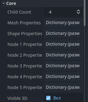
- Child Count - number of child nodes in the core
- Then dictionaries of node parameters for each cell (the dictionary is full if the cell is filled)
RayCast
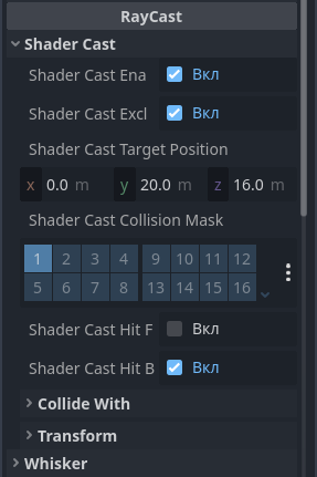
The RayCast category consists of two configuration sections for nodes built into the core: ShaderCast and Whisker.
Whisker monitors collisions and works in conjunction with y and z-sorting to render objects correctly. It is an Area3D node and determines whether an object is behind a barrier or not.
Info
For Whisker to work correctly, it is shifted 1.1 meters forward (adjust this value if your object is not a 1x1x1 cube). This is necessary to avoid unnecessary potential collisions with other objects that interact with the core.
In addition, the Shape for Whisker should be slightly smaller than the expected collision zone. This is required to avoid false collisions due to incorrect calculations by the engine itself (related to the problem of float numbers).
For example, if the estimated collision zone is a 1x1x1 cube, then the Shape size is 0.9x0.9x0.9.
ShaderCast is a special-purpose node. Its purpose is to detect collisions with objects in front of the player and draw a shader based on this.
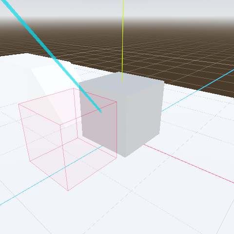
Whisker zone
Blue ray is ShaderCast